Front End
The front end include two types of optical flow: frame to frame optical flow and patch optical frame.
Initialization
The front end is initialized in
func param: vio_config: parameters in config.json file; calib: camera info.
return: OpticalFlowBase::Ptr, which is reset (initialized) by config.optical_flow_type and config.optical_flow_pattern parameter shown in the table.
The input_queue is set to be the stereo image buffer queue with tbb::concurrent_bounded_queue to handle multithread sharing. The output_queue passes to vio vision_data_queue.
Parameters
| param | type | value used | function |
|---|---|---|---|
| config.optical_flow_type | "frame_to_frame" / "patch" | "frame_to_frame" | decide optical flow method: "patch" to use PatchOpticalFlow and "frame_to_frame" to use FrameToFrameOpticalFlow |
| config.optical_flow_pattern | 24/52/51/50 | 50 | optical flow pattern shown in the below image |
data structure
FrameToFrameOpticalFlow
Constructor
- calculate R and T between if there is more than one cameras.
- initialize the
processingLoop()thread and use a smart pointer to handle resource.
processingLoop
Keep poping OpticalFlowInput from the input_queue and process it with processFrame(input_ptr->t_ns, input_ptr) function until we get a nullptr from the input_queue.
processFrame
Input(int64_t curr_t_ns, OpticalFlowInput::Ptr& new_img_vec)
first frame initialization
- initialize transforms (OpticalFlowResult::Ptr)
- initialize pyramid(std::shared_ptr<std::vector<basalt::ManagedImagePyr<u_int16_t>>>)
- running pyramid for all images in parallel
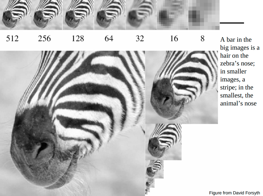
The ManagedImagePyr class is used to calculate pyramid of the input image. Noted that the pyramid is stored as a (1+1/2)w x h image shown as the zebra image. A gaussian kernel is used to subsampling the image and every even-numbered row and colum have to be removed. The kernel is shown as this template.
The paramid 0,1...n are stored from left to right and upper to bottom as shown in the image.

- addPoints
- add previously points from the Left image to pts0(vector<Eigen::Vector2d>) variable
- detect points at level 0
- put corners with keypoint_id in transform(local variable) and initialize new_poses0(same type as transform: Eigen::AffineCompact2f). note: transfrom is just the keypoint location on image
- track points from left to right
- filterPoints
supporting functions
- trackPoints
Track pointss between two images pyramid. Images could be from left to right/ right to left and previous to current. Noted that parameter without const here means output of the function. Also pay attention to the name, transform_map and transforms are map and vector, while transform is a single keypoint from the containers. It also applies to functions such as trackpoints and trackpoint.
- trackpoint Track point from coarse to fine at all levels. The point is tracked from old_pyramid to current pyramid.
- trackPointAtLevel Track one point at one pyramid level. Return patch_valid, which means
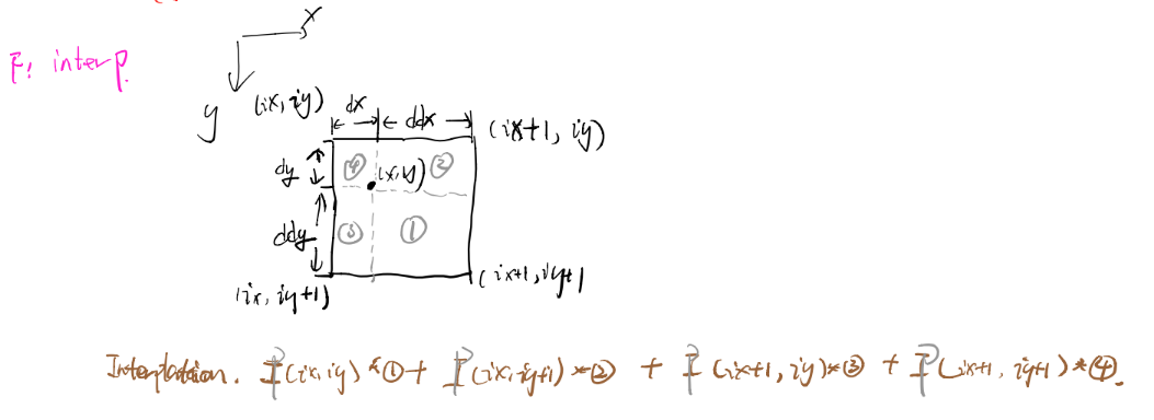
- OpticalFlowPatch structure This structure is used to buid a patch around a point in image, and provides function to calculate residual used for transform itertation. Noted that below are pseudo code only.
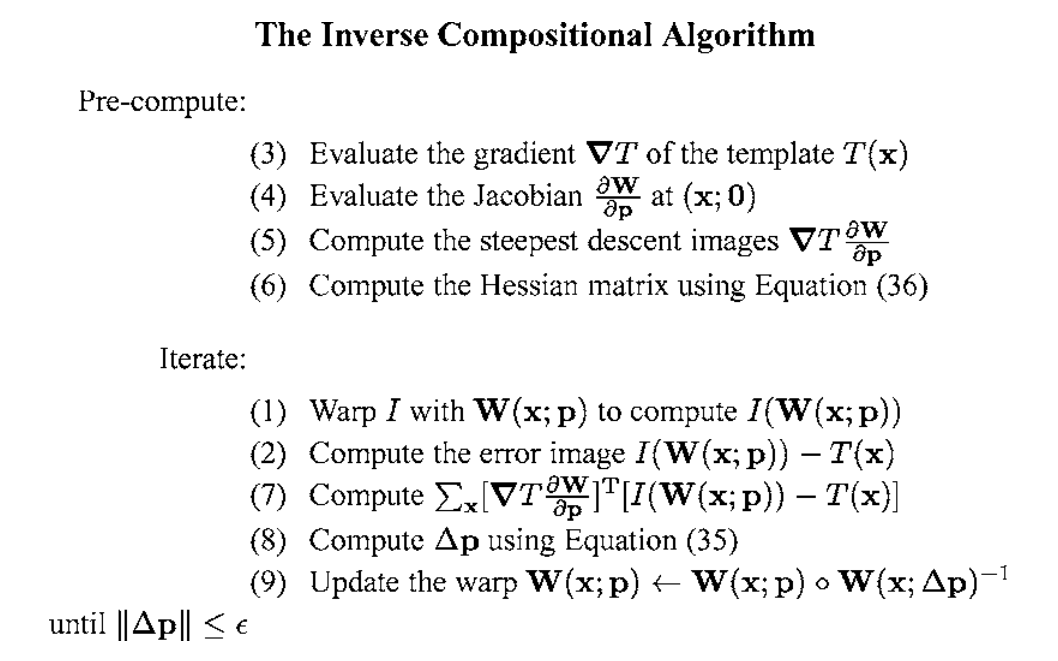
Using the inverse compositional algorithm discribed in section 3.2.1 in Lucas-Kanade 20 Years On: A Unifying Framework
The original problem is to minimize the sum of squard error between two images, the template and the image warped back on to the coordinate frame of the template:
We could assume that a current estimate of p is known and then iteratively solves for increments to the parameters , i.e. the following expression is minimized:
Forwards additive(Lucas-Kanade) algorithm: or
Frowards compositional algorithm:
However, in order to avoid a huge computational cost in re-evaluating the Hessian in every iteration, we switch the role of the image and the template to form the inverse problem, where the goal is to minimize:
with respect to and then update the warp:
Performing a first order Taylor expansion gives:
The solution to this least-squares problem is:
where H is:
Noted that the Jacobian is evaluated at (x;0) and since there is nothing in the Hssian that depends on p, it is constant across iterations and can be pre-computed. The detail diagram of the algorithm is as follow.

In Baslt, W is group SE(2),which is rigid transformations in 2D space. It has 3 degree of freedom: . The derivative of SE(2) is a 2x3 matrix , where means template gradient and means the change of x or y with respect to SE2 parameters . For details can check out Equ. 117 in SE2. SE2 can be represented by:
And . Thus we have:


frame processing
Draft section
pitch; ///Yu: Bytes per unit data. e.g: one row contain pitch * w bytes.